環境
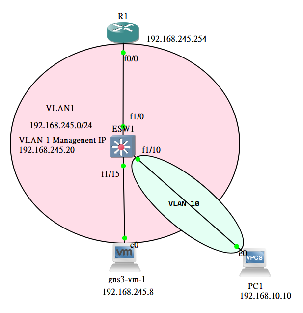
這邊配置一台 L3 交換器、路由器、VM 和 PC。這一次實驗主要是實現單臂路由(router-on-a-stick),單臂路由簡單來說是用來實現不同 VLAN 間的通訊,其接口需配置 trunk 協定,在藉由一個接口建立每個 VLAN 的網路 gateway。當 VLAN 有設置後,其每個封包都會帶著 VLAN 標籤,而這個標籤會在設定單臂路由的路由器進行解析,這樣就能讓不同 VLAN 可以相互通訊。至於 VLAN 相關操作和原理可查看之前寫的內容。
配置 ESW1 交換器與 R1 路由器
將接口啟動,並使用 hostname 配置 ESW1 的主機名稱。
ESW1#conf t
ESW1(config)#hostname IT@L3
% Hostname contains one or more illegal characters.

% Hostname "IT@L3" is not a legal LAT node name, Using "CISCO_18F100"
IT@L3(config)#interface fastEthernet 1/0
IT@L3(config-if)#no shutdown
IT@L3(config-if)#interface fastEthernet 1/15
IT@L3(config-if)#no shutdown
IT@L3(config-if)#exit
配置 telnet 相關配置以及交換機上安全設定,有關 telnet 配置可參考之前文章所做的實驗。
IT@L3(config)#username cisco password cisco@123
IT@L3(config)#line vty 0 4
IT@L3(config-line)#login local
IT@L3(config-line)#transport ?
  input      Define which protocols to use when connecting to the terminal
             server
  output     Define which protocols to use for outgoing connections
  preferred  Specify the preferred protocol to use

IT@L3(config-line)#transport input ?
  all      All protocols
  lapb-ta  LAPB Terminal Adapter
  lat      DEC LAT protocol
  none     No protocols
  pad      X.3 PAD
  rlogin   Unix rlogin protocol
  ssh      TCP/IP SSH protocol
  telnet   TCP/IP Telnet protocol
  udptn    UDPTN async via UDP protocol
  v120     Async over ISDN
IT@L3(config-line)#transport input telnet
IT@L3(config)#enable password 12345
IT@L3(config)#enable secret 123456
IT@L3(config)#service password-encryption
IT@L3(config)#banner ?
  LINE            c banner-text c, where 'c' is a delimiting character
  exec            Set EXEC process creation banner
  incoming        Set incoming terminal line banner
  login           Set login banner
  motd            Set Message of the Day banner
  prompt-timeout  Set Message for login authentication timeout
  slip-ppp        Set Message for SLIP/PPP
IT@L3(config)#banner motd #
Enter TEXT message.  End with the character '#'.
Unauthorized Access
#
IT@L3(config)#ip default-gateway 192.168.245.254
建立 VLAN 1 的 SVI(Switched Virtual Interface),藉由此 SVI 可讓我們從 VM 中登入作業。至於為什麼是 VLAN 1 原因就是預設的網路接口都是 VLAN 1。
IT@L3(config)#interface vlan1
IT@L3(config-if)#ip address 192.168.245.20 255.255.255.0
IT@L3(config-if)#no shutdown
設定完上述之後,我們可以嘗試連通,以及 telnet 遠端。
VM ping vlan1 虛擬接口

telnet ESW1

預設情況下都是使用 VLAN 1
IT@L3(config)#do sh vlan-switch

VLAN Name                             Status    Ports
---- -------------------------------- --------- -------------------------------
1    default                          active    Fa1/0, Fa1/1, Fa1/2, Fa1/3
                                                Fa1/4, Fa1/5, Fa1/6, Fa1/7
                                                Fa1/8, Fa1/9, Fa1/10, Fa1/11
                                                Fa1/12, Fa1/13, Fa1/14, Fa1/15
1002 fddi-default                     active
1003 token-ring-default               active
1004 fddinet-default                  active
1005 trnet-default                    active

VLAN Type  SAID       MTU   Parent RingNo BridgeNo Stp  BrdgMode Trans1 Trans2
---- ----- ---------- ----- ------ ------ -------- ---- -------- ------ ------
1    enet  100001     1500  -      -      -        -    -        1002   1003
1002 fddi  101002     1500  -      -      -        -    -        1      1003
1003 tr    101003     1500  1005   0      -        -    srb      1      1002
1004 fdnet 101004     1500  -      -      1        ibm  -        0      0
1005 trnet 101005     1500  -      -      1        ibm  -        0      0
配置 R1 的 f0/0。配置完後,使用 VM 去 ping 該 R1 的 f0/0,預設都在 Vlan 1 又是同一網段因此都是可以互通。
R1(config)#interface fastEthernet 0/0
R1(config-if)#ip address 192.168.245.254 255.255.255.0
R1(config-if)#no shutdown
設置 VLAN,本實驗中只有使用 vlan 10,其餘可以不新增。
IT@L3#vlan database
IT@L3(vlan)#vlan 10 name IT@L3-VLAN10
VLAN 10 added:
    Name: IT@L3-VLAN10
IT@L3(vlan)#vlan 20 name IT@L3-VLAN20
VLAN 20 added:
    Name: IT@L3-VLAN20
IT@L3(vlan)#vlan 100 name IT@L3-VLAN100
VLAN 100 added:
    Name: IT@L3-VLAN100
IT@L3(vlan)#exit
APPLY completed.
Exiting....
查看配置的 Vlan
IT@L3#show vlan-switch

VLAN Name                             Status    Ports
---- -------------------------------- --------- -------------------------------
1    default                          active    Fa1/0, Fa1/1, Fa1/2, Fa1/3
                                                Fa1/4, Fa1/5, Fa1/6, Fa1/7
                                                Fa1/8, Fa1/9, Fa1/10, Fa1/11
                                                Fa1/12, Fa1/13, Fa1/14, Fa1/15
10   IT@L3-VLAN10                     active # this
20   IT@L3-VLAN20                     active # this
100  IT@L3-VLAN100                    active # this
1002 fddi-default                     active
1003 token-ring-default               active
1004 fddinet-default                  active
1005 trnet-default                    active

VLAN Type  SAID       MTU   Parent RingNo BridgeNo Stp  BrdgMode Trans1 Trans2
---- ----- ---------- ----- ------ ------ -------- ---- -------- ------ ------
1    enet  100001     1500  -      -      -        -    -        1002   1003
10   enet  100010     1500  -      -      -        -    -        0      0
20   enet  100020     1500  -      -      -        -    -        0      0
100  enet  100100     1500  -      -      -        -    -        0      0
1002 fddi  101002     1500  -      -      -        -    -        1      1003
1003 tr    101003     1500  1005   0      -        -    srb      1      1002
新增一台 PC1 並配置其 IP 和 gateway,如下
PC1> ip 192.168.10.10/24 192.168.10.254
Checking for duplicate address...
PC1 : 192.168.10.10 255.255.255.0 gateway 192.168.10.254
新增完後將其 PC1 對應到 ESW1 的接口設置到 VLAN 10 進行綁定。
IT@L3(config)#interface fastEthernet 1/10
IT@L3(config-if)#switchport mode access
IT@L3(config-if)#switchport access vlan 10
IT@L3(config-if)#no shutdown
查看是否有被分配。
IT@L3(config)#do sh vlan-swit

VLAN Name                             Status    Ports
---- -------------------------------- --------- -------------------------------
1    default                          active    Fa1/1, Fa1/2, Fa1/3, Fa1/4
                                                Fa1/5, Fa1/6, Fa1/7, Fa1/8
                                                Fa1/9, Fa1/11, Fa1/12, Fa1/13
                                                Fa1/15
10   IT@L3-VLAN10                     active    Fa1/10 # this
20   IT@L3-VLAN20                     active
100  IT@L3-VLAN100                    active
1002 fddi-default                     active
1003 token-ring-default               active
...
在 R1 跟 ESW1 接口間,設置 Trunk 這表示所有不同 VLAN 可以透過這條 Trunk 進行通訊。
IT@L3(config)#interface fastEthernet 1/0
IT@L3(config-if)#switchport trunk encapsulation dot1q
IT@L3(config-if)#switchport mode trunk
查看 Trunk
IT@L3#show interfaces trunk

Port      Mode         Encapsulation  Status        Native vlan
Fa1/0     on           802.1q         trunking      1

Port      Vlans allowed on trunk
Fa1/0     1-1005

Port      Vlans allowed and active in management domain
Fa1/0     1,10,20,100

Port      Vlans in spanning tree forwarding state and not pruned
Fa1/0     1,10,20,100
在 R1 上設定單臂路由這樣使得所有 VLAN 透過這個設定以達到相互通訊。在連接 ESW1 的接口上個別設定 VLAN ID 的子接口,並將其賦予 VLAN 子網路的 gateway。
R1(config)#interface fastEthernet 0/0
R1(config-if)#no ip address
R1(config-if)#int fa 0/0.1
R1(config-subif)#encapsulation dot1Q 1
R1(config-subif)#ip address 192.168.245.254 255.255.255.0

R1(config-subif)#int fa 0/0.10
R1(config-subif)#encapsulation dot1Q 10
R1(config-subif)#ip address 192.168.10.254 255.255.255.0
查看有無配置
R1(config-subif)#do sh ip int brief
Interface                  IP-Address      OK? Method Status                Protocol
FastEthernet0/0            unassigned      YES manual up                    up
FastEthernet0/0.1          192.168.245.254 YES manual up                    up
FastEthernet0/0.10         192.168.10.254  YES manual up                    up
查看路由表
R1#show ip route
Codes: C - connected, S - static, R - RIP, M - mobile, B - BGP
       D - EIGRP, EX - EIGRP external, O - OSPF, IA - OSPF inter area
       N1 - OSPF NSSA external type 1, N2 - OSPF NSSA external type 2
       E1 - OSPF external type 1, E2 - OSPF external type 2
       i - IS-IS, su - IS-IS summary, L1 - IS-IS level-1, L2 - IS-IS level-2
       ia - IS-IS inter area, * - candidate default, U - per-user static route
       o - ODR, P - periodic downloaded static route

Gateway of last resort is not set

C    192.168.10.0/24 is directly connected, FastEthernet0/0.10
C    192.168.245.0/24 is directly connected, FastEthernet0/0.1
嘗試 PC1 ping VM 或反過來,此時應該是會通的,如果失敗需查看配置是否有誤。